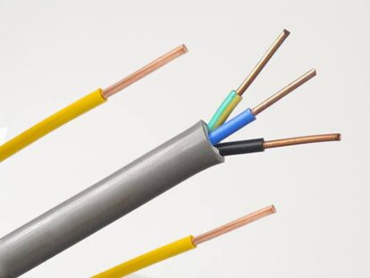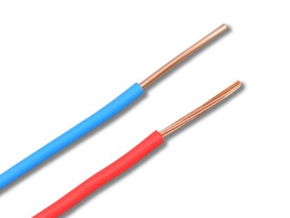
Solid or concentrically stranded bare copper. Copper is classified into three types: hard, moderately hard, and soft.
This conductor is also manufactured in accordance with BS7884, ASTM B8, NF C34-110, IEC 61089, DIN 48201-1, and other specifications.
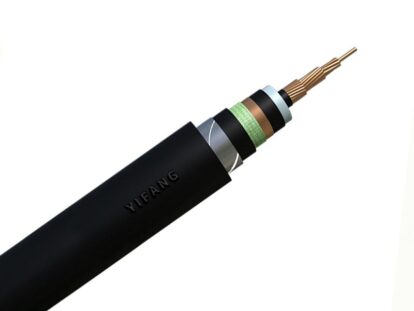
Features
- Hot-dip zinc coating that is uniform and firm.
- A bright, clean surface.
- Extremely high corrosion resistance.
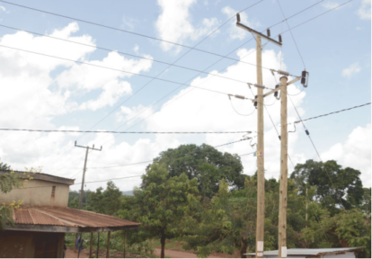
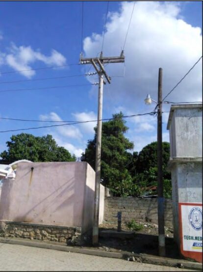
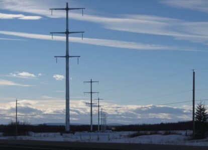
Application
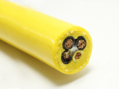
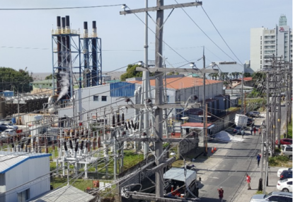
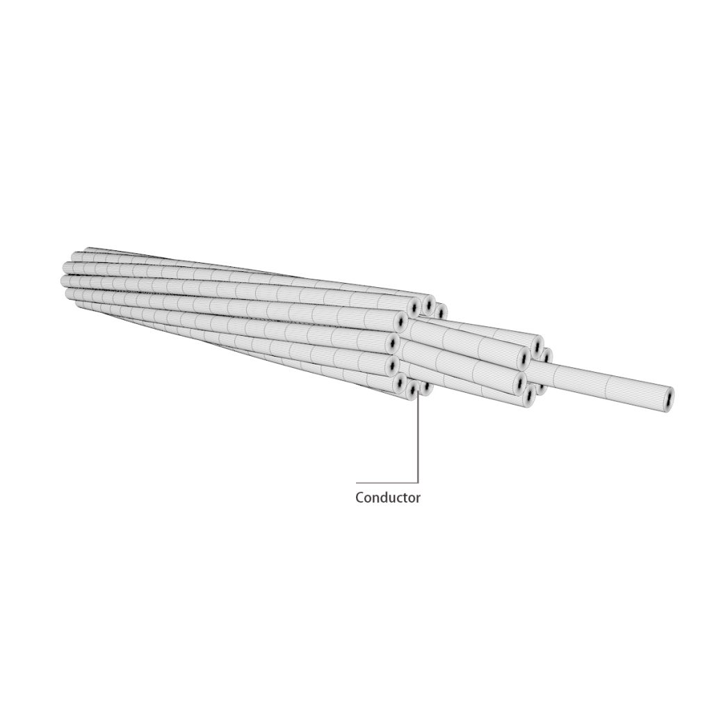
In overhead transmission and distribution applications, solid stranded bare copper is used. The more elastic stranded conductors are appropriate for grounding, jumpers, and uninsulated connections in electrical construction.
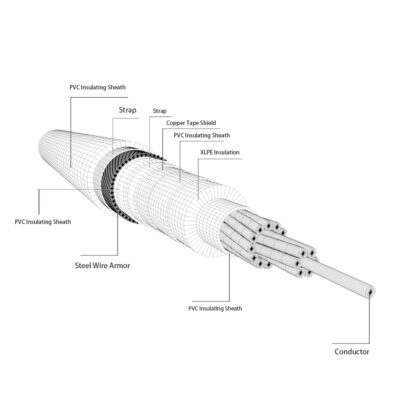
Construction
Copper wire, solid or stranded. Temperaments are available in hard, medium-hard, and soft. Multi-strand conductors are stranded concentrically in the hard and medium hard states, while combined single-strand stranding is used in the soft tensioned state.
Performance
Physical, mechanical and electrical properties of solid, circular, hard drawn copper wire
| Nominal area of cross-setion mm2 | Wire diameter Nominal mm | Wire diameter Max. mm | Wire diameter Min. mm | Nominal mass per unit length kg/km | Resitance at20°C Ω/km | Resitance at 20°C Ω/km | Minimum breaking load N |
| 1.43 | 1.35 | 1.364 | 1.337 | 12.73 | 12.41 | 12.66 | 583 |
| 2.01 | 1.60 | 1.616 | 1.584 | 17.87 | 8.838 | 9.018 | 818 |
| 2.27 | 1.70 | 1.717 | 1.683 | 20.18 | 7.829 | 7.988 | 923 |
| 2.54 | 1.80 | 1.818 | 1.782 | 22.62 | 6.983 | 7.125 | 1035 |
| 3.46 | 2.10 | 2.121 | 2.079 | 30.79 | 5.130 | 5.235 | 1409 |
| 3.98 | 2.25 | 2.273 | 2.228 | 35.35 | 4.469 | 4.558 | 1618 |
| 4.75 | 2.46 | 2.484 | 2.435 | 42.25 | 3.739 | 3.816 | 1932 |
| 4.91 | 2.50 | 2.525 | 2.475 | 43.64 | 3.620 | 3.694 | 1997 |
| 5.51 | 2.65 | 2.677 | 2.624 | 49.03 | 3.222 | 3.286 | 2244 |
| 6.16 | 2.80 | 2.828 | 2.772 | 54.74 | 2.886 | 2.944 | 2505 |
| 6.61 | 2.90 | 2.929 | 2.871 | 58.72 | 2.600 | 2.745 | 2687 |
| 7.07 | 3.00 | 3.030 | 2.970 | 62.84 | 2.514 | 2.565 | 2875 |
| 8.04 | 3.20 | 3.232 | 3.168 | 71.50 | 2.210 | 2.254 | 3271 |
| 9.90 | 3.55 | 3.586 | 3.515 | 87.99 | 1.795 | 1.881 | 4027 |
| 11.04 | 3.75 | 3.788 | 3.713 | 98.19 | 1.609 | 1.641 | 4494 |
| 14.52 | 4.30 | 4.350 | 4.250 | 129.1 | 1.224 | 1.253 | 5675 |
NOTE 2. Minimum breaking loads for nominal diameters up to and including 4 mm are based on the minimum diameter of conductor and a tensile strengh of 415 N/mm2 and for nominal diameters greater than 4 mm they are based on the mimimm diameter of conductor and a tensile strength of 400 N/mm2.
NOTE 3. Nominal mass per unit length has been calculated using a density of 8890 kg/m3.
Physical, mechanical and electrical properties of solid, circular, hard drawn copper alloy wire
| Nominal area of crosss-section | Wire diameter Nominal | Wire diameter Max. | Wire diameter Min. | Nominal mass per unit length | Resistance at 20°C | Resistance at 20°C | Minimum breaking load |
| mm2 | mm | mm | mm | kg/km | Ω/km | Ω/km | N |
| 2.27 | 1.7 | 1.717 | 1.683 | 20.30 | 9.494 | 9.687 | 1379 |
| 2.54 | 1.80 | 1.818 | 1.782 | 22.76 | 8.469 | 8.641 | 1546 |
| 3.14 | 2.00 | 2.020 | 1.980 | 28.10 | 6.860 | 6.999 | 1909 |
| 3.46 | 2.10 | .2.121 | 2.079 | 30.98 | 6.222 | 6.348 | 2105 |
| 3.98 | 2.25 | 2.273 | 2.228 | 35.57 | 5.420 | 5.527 | 2417 |
| 4.15 | 2.30 | 2.323 | 2.277 | 37.16 | 5.187 | 5.292 | 2525 |
| 4.91 | 2.50 | 2.525 | 2.475 | 43.91 | 4.390 | 4.479 | 2983 |
| 5.31 | 2.60 | 2.626 | 2.574 | 47.49 | 4.059 | 4.141 | 3226 |
| 6.16 | 2.80 | 2.828 | 2.772 | 55. 08 | 3.500 | 3.571 | 3561 |
| 6.61 | 2.90 | 2.929 | 2.871 | 59.08 | 3.263 | 3.329 | 3820 |
| 8.04 | 3.20 | 3.232 | 3.168 | 71.94 | 2.680 | 2.734 | 4651 |
| 9.62 | 3.50 | 3.535 | 3.465 | 86.06 | 2.240 | 2.285 | 5564 |
| 10.75 | 3.70 | 3.737 | 3.663 | 96.18 | 2.004 | 2.045 | 5901 |
| 12.57 | 4.00 | 4.040 | 3.960 | 112.4 | 1.715 | 1.750 | 6897 |
| 14.52 | 4.30 | 4.350 | 4.250 | 129.9 | 1.484 | 1.519 | 7944 |
NOTE 2. Nominal mass per unit length has been calculated using a density of 8945 kg/m3 and therefore the values apply only to copper-cadmium alloy C108.
Physical, mechanical and electrical properties of hard drawn copper stranded conductors
| Nominal area of cross-section of stranded conductor mm2 | Construction(stranding and wire diameter) number/mm | Overall diameter of conductor (approx.) mm | Nominal mass per unit length kg/km | Resistance at 20°C Nominal Ω/km | Resistance at 20°C Max Ω/km | Minimum breaking load N |
| 10 | 7/1.35 | 4.05 | 89.82 | 1.788 | 1.829 | 3752 |
| 14 | 7/1.60 | 4.80 | 126.2 | 1.273 | 1.303 | 5267 |
| 16 | 3/2.65 | 5.70 | 148.3 | 1.082 | 1.106 | 6194 |
| 16 | 7/2.10 | 5.10 | 142.4 | 1.128 | 1.154 | 5946 |
| 25 | 7/2.10 | 6.30 | 217.3 | 0.7391 | 0.7563 | 9073 |
| 32 | 3/3.75 | 8.06 | 296.9 | 0.5405 | 0.5520 | 12400 |
| 32 | 7/2.46 | 7.38 | 298.2 | 0.5386 | 0.5497 | 12442 |
| 35 | 7/2.50 | 7.50 | 308.0 | 0.5215 | 0.5337 | 12860 |
| 50 | 7/3.00 | 9.00 | 443.5 | 0.3622 | 0.3706 | 18520 |
| 50 | 19/1.80 | 9.00 | 435.8 | 0.3727 | 0.3819 | 17700 |
| 70 | 7/3.55 | 10.65 | 621.1 | 0.2586 | 0.2646 | 25930 |
| 70 | 19/2.10 | 10.50 | 593.2 | 0.2738 | 0.2806 | 24090 |
| 95 | 19/2.50 | 12.50 | 840.7 | 0.1932 | 0.1980 | 34140 |
| 100 | 7/4.30 | 12. 90 | 911.2 | 0.1763 | 0.1810 | 36540 |
| 120 | 19/2.80 | 14.00 | 1055 | 0.1540 | 0.1578 | 42830 |
| 125 | 19/2 .90 | 14.50 | 1131 | 0.1436 | 0.1471 | 45940 |
| 150 | 19/3.20 | 16.00 | 1377 | 0.1180 | 0.1208 | 55940 |
| 150 | 37/2.25 | 15.75 | 1334 | 0.1233 | 0.1264 | 53880 |
| 185 | 19/3.55 | 17.75 | 1695 | 0.09582 | 0.09815 | 68860 |
| 185 | 37/2 .50 | 17.50 | 1647 | 0.09981 | 0.1024 | 66490 |
NOTE 2. Minimum breaking load is based on the sum of minimum breaking loads of component wires shown in table 2, multiplied by a factor of 0.92 for three and seven wire standards and 0.90 for nineteen and thirty-seven wire strands.
NOTE 3. Nominal mass per unit length has been calculted using a density of 8800 kg/m3
Physical, mechanical and electrical properties of hard drawn copper alloy stranded conductors
| Nominal area of cross-section of stranded conductor mm2 | Construction (stranding and wire diameter) number/mm | Overall diameter of conductor (approx.) | Nominal mass per unit length kg/km | Resistance at 20°C Nominal Ω/km | Resistance at 20°C Max Ω/km | Minimum breaking load N |
| 12 | 3/2.30 | 4.95 | 112.4 | 1.743 | 1.780 | 6968 |
| 16 | 7/1.70 | 5.10 | 143.3 | 1.368 | 1.399 | 8883 |
| 22 | 7/2.00 | 6.00 | 198.3 | 0.9882 | 1.011 | 12290 |
| 25 | 7/2.10 | 6.30 | 218.7 | 0.8959 | 0.9171 | 13550 |
| 30 | 7/2.30 | 6.90 | 262.3 | 0.7469 | 0.7645 | 16260 |
| 35 | 7/2.50 | 7.50 | 309.9 | 0.6324 | 0.6471 | 19210 |
| 38 | 7/2.60 | 7.80 | 335,2 | 0.5847 | 0.5983 | 20780 |
| 45 | 7/2.90 | 8.70 | 417.0 | 0.4698 | 0.4809 | 24600 |
| 55 | 7/3.20 | 9.60 | 507.8 | 0.3859 | 0.3950 | 29950 |
| 70 | 19/2.10 | 10.50 | 596.8 | 0.3316 | 0.3403 | 35990 |
| 75 | 7/3.70 | 11.10 | 678.8 | 0.2887 | 0.2954 | 38010 |
| 95 | 19/2 .50 | 12.50 | 845.9 | 0.2343 | 0.2400 | 51010 |
| 100 | 7/4.30 | 12.90 | 916.9 | 0.2138 | 0.2195 | 51160 |
| 120 | 19/2.80 | 14.00 | 1061 | 0.1862 | 0.1914 | 60890 |
| 125 | 19/2. 90 | 14.50 | 1138 | 0.1739 | 0.1784 | 65310 |
| 150 | 19/3.20 | 16.00 | 1386 | 0.1428 | 0.1465 | 79530 |
| 150 | 37/2.25 | 15.75 | 1342 | 0.1493 | 0.1533 | 80490 |
| 180 | 19/3.50 | 17.50 | 1658 | 0.1196 | 0.1225 | 95140 |
| 180 | 37/2.50 | 17.50 | 1657 | 0.1209 | 0.1242 | 99330 |
| 200 | 19/3.70 | 18.50 | 1853 | 0.1068 | 0.1696 | 100900 |
| 240 | 19/4. 00 | 20.00 | 2165 | 0.09153 | 0.09378 | 117900 |
NOTE 2. Minimum breaking load is based on the sum of minimum breaking loads of component wires shown in table 3, multiplied by a factor of 0.92 for there and seven wire standards and 0.90 for nineteen and thirty-seven wire strands.
NOTE 3. Nominal mass per unit length has been calculted using a density of 8945 kg/m3 and therefore the values appy only to copper-cadmium alloy C108.
Lay ratios of stranded conductors
| Number of wires in conductor | lay ratio 3 wire layer Min. | lay ratio 3 wire layer Max. | lay ratio 6 wire layer Min. | lay ratio 6 wire layer Max. | lay ratio 12 wire layer Min. | lay ratio 12 wire layer Max. | lay ratio 18 wire layer Min. | lay ratio 18 wire layer Max. |
| 3 | 11 | 16 | - | - | - | - | - | - |
| 7 | - | - | 13 | 17 | - | - | - | - |
| 19 | - | - | 13 | 17 | 12 | 15 | - | - |
| 37 | - | - | 13 | 17 | 12 | 15 | 10.5 | 13 |